Wednesday, November 20, 2013


Wednesday, November 13, 2013
Manufacturing in Motion
 |
| Team members Jose and Ryan with their work of art. |
- Digger brake
- drilling of digger plate
- Spindle
- material was cut
- Mounting bracket
- drilled
- mounted (as shown in picture)
To be done:
Tap upright and thread front axle to have spindle ready for welding.
Receive remaining material and begin prep work for welding.
Wednesday, November 6, 2013
Steering design Completed

To-do:
Use the updated bill of materials to purchase materials for:
- Steering
- Suspension
- Top frame
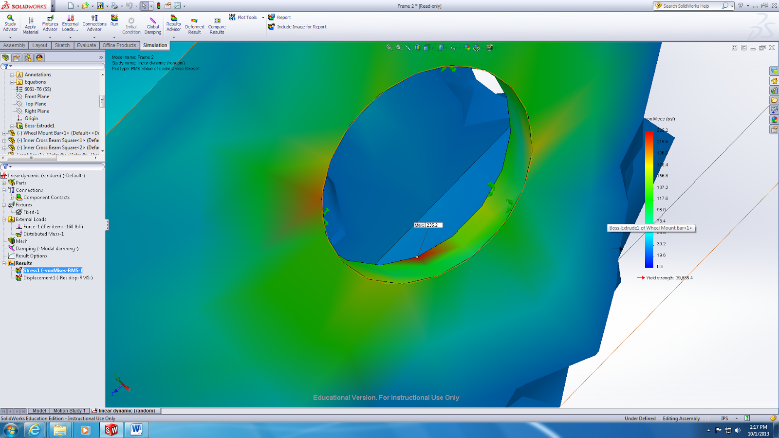
Spindle Static Analysis
 | |
|
 | |
|
 |
| Static Analysis of 700 lbs |
Wednesday, October 23, 2013
Moving forward
This week was very informative as we conducted analysis on our spindle/axel set up. Further test will be done to confirm our results.
As we move forward, completion of the rear wheel assembly is needed in order to finish welding the base of our frame.
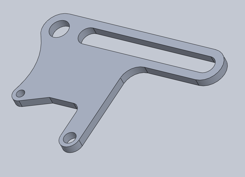
Below is an image of a new bracket needed to complete this design.

Wednesday, October 16, 2013

Welding Setback
This week, the team was set back on welding due to design. A few of the cart's components must be redesigned in order to continue welding:


- spindle
- suspension arms (possibly)
- reinforcement of front wheel (new design)


To-do:
Finalize design for mentioned components and run through our machinists (Mike and Joe) in order to proceed with welding.
Thursday, October 10, 2013
Lauren the Machinist
Today, we have a special entry, as our team member Lauren learns how to use a mill.


Monday, October 7, 2013
Frame Material Purchased
With a completed cut plan, material(Aluminum 6061-T6) was ordered and cutting began almost immediately.


To do:
Prepare the aluminum by Wednesday and begin welding late this week, possibly Monday (10/14/13)


Prepare the aluminum by Wednesday and begin welding late this week, possibly Monday (10/14/13)
Wednesday, October 2, 2013
Bottom Frame Static Analysis
With the bottom frame finalized, static analysis was done to simulate a pulling force of 500 pounds.
The analysis produced the following results.

To do:
Further analysis will be on suspension
Create caliper mounting bracket if needed.
Buy material to begin welding frame.
Tuesday, October 1, 2013
Spindle Assembly

With the purchase of the disc brakes and calipers, the team encountered problems with the caliper's mounting bracket. A solution was proposed that would allow the mounting bracket to be attached to the entire frame via the designed spindle assembly.
Wednesday, September 25, 2013
Top Frame Of Cart On The Design Table

The team brainstormed a lot about the top of the frame. Things concerning the top frame that were discussed were:
- collapsible vs. detachable
- drill patterns
- overall design.
To-do in the coming week.
- Talk to our school machinist (Mike and Joe) about a machining plan and where to buy material.
- New bearings needed for the wheels and the top of the frame.

Wednesday, September 18, 2013
The Buying Process Begins!
The weekend was very productive with several critical purchases being made. The items purchased were all four wheels/tires and brake assembly. A final base frame will be designed with the following dimensions in consideration.

- Diameter of wheels ~18 in
- Width of wheels with brake assembly ~ 4 in (2.94in wheels only)
- Axel diameter - 15mm
The top portion of the frame is also in the design process with generic lengths (will change with the final dimensions of the base). See below
In the week to come, the team will research the cost of material needed for the entire frame based on our design.
Tuesday, September 17, 2013
Solid Model of A-Arms


Wednesday, September 11, 2013


Critical decisions
This week the team made a few critical decisions. With an updated gantt chart, the team realized they're were behind schedule therefore the following decisions were made.
- Round tuning was thrown out and square tubing was chosen
1.5 x 2 inch - Created a buying list for the following items:
- Wheels
- Brakes
- Tires
- Shock absorber
- Tie-rods
For the coming week, the teams plans to have items on the buying list on order by no later than Monday (Sept 16, 2013)
Wednesday, September 4, 2013
First Meeting of the 2nd Semester
The team met to discuss future plans on the mushing cart's construction as well as revisited the work that was done before the summer. With each individual teammate having a different schedule during the summer, a lot of scheduled items were pushed back. Therefore the team brought up topics that needed to be completed in order to get the building process in motion.
The team decided focus on the items that need to be purchased. A few items that will be purchased are:


The team decided focus on the items that need to be purchased. A few items that will be purchased are:
- Wheels & Tires*

- Disc Brakes*
- Shock Absorbers*

*Items pictured may not be used in the final product.
Thursday, May 16, 2013
Action Items
Action Items: Entire
Project
|
5/5/2013
|
||
Task
|
Status
|
Lead
|
|
Sketch
|
|||
dimensions configured
|
DONE
|
all
|
|
components chosen
|
DONE
|
all
|
|
research
|
NA
|
all
|
|
Model (Solid Works)
|
|||
brake system
|
21-Jun
|
Ashley
|
|
shock system
|
21-Jun
|
Jose
|
|
steering system
|
21-Jun
|
Ryan
|
|
frame
|
21-Jun
|
Lauren, Rochelle
|
|
entire assembly
|
28-Jun
|
||
Analysis
|
|||
tubing
|
14-Jun
|
Lauren, Rochelle
|
|
frame
|
21-Jun
|
Lauren, Rochelle
|
|
entire assembly
|
28-Jun
|
||
Budget
|
|||
configure budget
|
DONE
|
all
|
|
generate parts list
|
|||
brake system
|
12-Jul
|
Ashley
|
|
shock system
|
12-Jul
|
Jose
|
|
steering system
|
12-Jul
|
Ryan
|
|
frame
|
12-Jul
|
Lauren, Rochelle
|
|
get quotes for material
|
|||
brake system
|
26-Jul
|
Ashley
|
|
shock system
|
26-Jul
|
Jose
|
|
steering system
|
26-Jul
|
Ryan
|
|
frame
|
26-Jul
|
Lauren, Rochelle
|
|
fundraisers
|
TBD
|
all
|
|
distribute funds
|
2-Aug
|
||
generate Pos
|
16-Aug
|
||
Buy All Needed Parts
|
|||
brake system
|
30-Aug
|
Ashley
|
|
shock system
|
30-Aug
|
Jose
|
|
steering system
|
30-Aug
|
Ryan
|
|
frame
|
30-Aug
|
Lauren, Rochelle
|
|
Assembly
|
|||
Frame
|
|||
generate a machining plan
|
30-Aug
|
||
machine all necessary parts
|
4-Oct
|
||
Weld all necessary components
|
1-Nov
|
||
Steering
|
|||
machine all necessary parts
|
4-Oct
|
||
assemble components
|
1-Nov
|
||
integrate into final assembly
|
22-Nov
|
||
Brake System
|
|||
machine all necessary parts
|
4-Oct
|
||
Assemble components
|
1-Nov
|
||
Integrate into final assembly
|
22-Nov
|
||
Shock System
|
|||
machine all necessary parts
|
4-Oct
|
||
assemble components
|
1-Nov
|
||
integrate into final assembly
|
22-Nov
|
||
Final Assembly
|
|||
integrate all components together
|
22-Nov
|
||
integrate collapsibility
|
22-Nov
|
||
check for safety measures
|
22-Nov
|
||
Assembly Testing and Analysis
|
|||
define testing procedures
|
22-Nov
|
||
run tests
|
6-Dec
|
||
analyze test results
|
13-Dec
|
||
Final Report
|
|||
generate report
|
20-Dec
|
Rochelle
|
|
generate presentation
|
20-Dec
|
Rochelle
|
|
Proposed Designs
The most completed system of the final design is the
chassis. It will be made out of 6061-T6
aluminum round tubing. A couple different diameters will be used to accommodate
the different amounts of strength needed in each area, while remaining somewhat
standardized.

The
structure of the suspension will be made of hollow steel tie rods and will use
rear bicycle shocks as the shock absorbers.
The specific lengths of the tie rods and the load capacity of the shock
absorbers still need to be determined.

The steering system will also be
comprised primarily of tie rods as well.
They form a four bar linkage to transfer rotation from bicycle
handlebars in the back to the front. At
the front the front bar of the linkage will be connected to the wheel
mounts. Exact dimensions must be
calculated to acquire the desired turning radius.

The
wheels and braking system will be primarily purchased. The brakes will include a hydraulic disk
brake on each wheel as well as a “digger” brake.
The
collapsible portion of the cart still must be designed. The primary function of this portion is to
support the steering handlebars and provide something for the passenger to hold
onto. This will likely be made of some
form of lightweight tubing, but dimensions and materials are yet to be
determined.
Tuesday, April 23, 2013
Suspension
The current focus of the team at this moment is the suspension. The importance of the suspension is high, the team must establish a design that allow the user of the mushing cart to maneuver the vehicle safely from a rear position while all the pivoting wheels are located on the front of the cart.
After searching for ideas, the team was able to find an off-road handcycle used for extreme sports by the handicap.

After searching for ideas, the team was able to find an off-road handcycle used for extreme sports by the handicap.

Inspired by the design, the team hope to use this for their mushing cart with steering being possible from a rear position.
Solid modeling has begun on the suspension system, and the team hopes to have those completed in the near future.
Tuesday, April 16, 2013


Sunday, April 7, 2013
Decision Making
Over the Spring break, the team met to make further decisions on the urban mushing cart. The following are possible options that we have narrowed down for the use of our chassis.
- Square vs. Round Tubing
- Thickness of material
- 4130 Alloy Steel (Chromoly) vs. 606-T6 Aluminum

Pros:
- Easier to weld
Cons:
- Load concentration areas

Pros:
- Cheap
- Widely Available
Cons:
- Harder to weld/bend
Future tasks
- Budget
- The team also spoke about funding for the cost of the material. The budget is currently $1000, but in the case that budget will be exceeded the team has determine that fundraising will be a necessity. The team has contacted fundraising coordinators at Warner Brothers Studios to attend TV show tapings in the event that more funds are needed.
- CAD
- A few things that the team will be working on in the following weeks is create rough CAD designs in order to get an idea of what materials will be more advantages. This task will also assist in determining what material and shape we should use when our CAD designs undergo static analysis.
Wednesday, March 27, 2013
Finalizing the Design
The team set limits for components in order to prepare for narrowing the options of components in an attempt to finalize the design. Below is what the team established:

=

where,
- Tires
- Length of frame
- Double barrel lever disk brakes
- Height of frame
- Steering
- Suspension
- Digger brake
- Hitch
The Decisions that were made were made the week of the (3/18/13) were:
- Tires
- Buy
- Size: 12-16 inches (in diameter)
- Frame (length & height)
- Build frame
- 6ft. x 3.5ft. x 3ft.(L x W x H) in approximation
- Brakes
- Buy
- Double barrel lever (disk brakes)
- On all four wheels
- Steering
- Make handlebars
- Buy handlebar grips
- Front steering
- Suspension
- Buying
- Front suspension
- Digger Brake
- Make
- Hitch
- Make
- Hook to carabiner
With certain areas of the design still in a grey area, the team will work together to fully complete the design by establishing how the suspension will work together with the steering. The steering will also be looking into, currently the idea is to create a four-bar linkage that connect from the back to the front, in order to steer from the back. Finally the team will also finalize whether the cart will have both front and back suspension or just front suspension.
Wednesday, March 13, 2013
Urban Mushing Cart Visits The Team

The team gathered on campus to examine the client's own mushing cart to gather information and ideas on how to improve on their design.

Wednesday, March 6, 2013
PDS
| Attribute | Type | Metric/Requirement | Unit | Notes |
| Safe | Objective | # of ways to cause bodily harm | ||
| Resilliance | Objective | Varying impact and Temp. | Force/Temp. | |
| Low-Cost | Objective | less than $1000 | Dollars | |
| Low-Weight | Objective | less then 85lb | Pounds | |
| User Friendly | Objective | Ease of transport | ||
| Regulate Speed | Function | Accelerate as fast as dogs/80% efficiency | ||
| Regualte Direction | Function | Change alignment within 5 secods | Time | |
| Decrease Speed | Function | Decelerate from 30-0MPH | MPH | |
| Stopping must range from 50-100ft | Feet | |||
| Stabalize Driver | Function | Reaction force must be less than 2/3 of impact force | lbf | |
| Secure Passenger | Function | Hold lateral force of 500lbf | lbf | |
| Attach Dogs | Function | Sustain tensile forces of 250lbf/dog | lbf | |
| Transfer Energy | Function | Transer Kinetic Energy of at least 25% | ||
| Absorb Impact | Function | absorb 60lbf of impact | lbf | |
| Prevent Damage | Function | Components must hold 60% of yield strength |
Subscribe to:
Comments (Atom)